Decoding a Siemens RCR10/433 Thermostat Signal to Control a Boiler from a Raspberry Pi
Posted on Monday, 23rd November 2015
This is a quick post in response to a question related to my boiler control Github project: https://github.com/rossharper/boilercontrol I intend to eventually perform a more comprehensive write-up of this whole project.
Background
I had been looking to start tinkering with my Raspberry Pi and do some home automation for a while. We have a Siemens RCR10/433 wireless thermostat programmer that controls our boiler and I wondered if it would be possible to hack the radio signal and take control of the boiler myself. Thus, I could create my own smart heating system inspired by products such as Nest and Hive. This post roughly outlines the process I used to sniff the signals sent between the thermostat and the receiver relay that controls the physical call for heat signal to the boiler.
Research
A quick Google search and I’d found some other people that had tried to do a similar thing with their boilers. First up, Steven Hale, who had a couple of great posts about Reverse Engineering a Worcester-Bosch DT10RF wireless thermostat in which he sniffs his thermostat’s signals and a further post with the detail of how he built a Soundcard Logic Analyser to do the sniffing. Secondly, I found a similar post (https://damn.technology/controlling-british-gas-wr1-receiver-arduino) detailing the same method of sniffing the thermostat’s radio signal. I identified that my thermostat uses the same radio frequency as those in the above posts: 433MHz (the clue is in the product name!). Perfect, I had something to go on. 433MHz transmitter and receiver ordered….
Sniffing the Signals
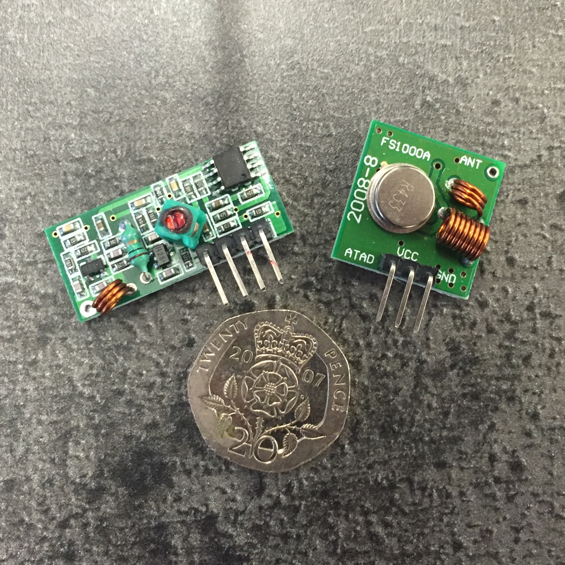
Once I had my 433MHz transmitter and receiver, I wired them up using a prototyping breadboard to my Raspberry Pi in a vain attempt to simply read the signals straight out of the air. The plan was to listen to the signal on the receiver’s data port whilst operating the thermostat to trigger its signals. No luck. The software I was using on the Raspberry Pi did not produce any results. Presumably the encoding used by my thermostat is non-standard. (I don’t remember the software off the top of my head. RC Switch, perhaps?)
So, the easy approach didn’t work — it was time to follow the posts mentioned above and build the ghetto-style logic analyser.
For this, I needed to buy the following:
- a length of shielded stereo cable (I tried with some old earphone cable at first but it was too thin)
- a 3.5mm stereo jack
- some 18k resistors
- some 82k resistors (I already had some wires, solder, and a soldering iron).
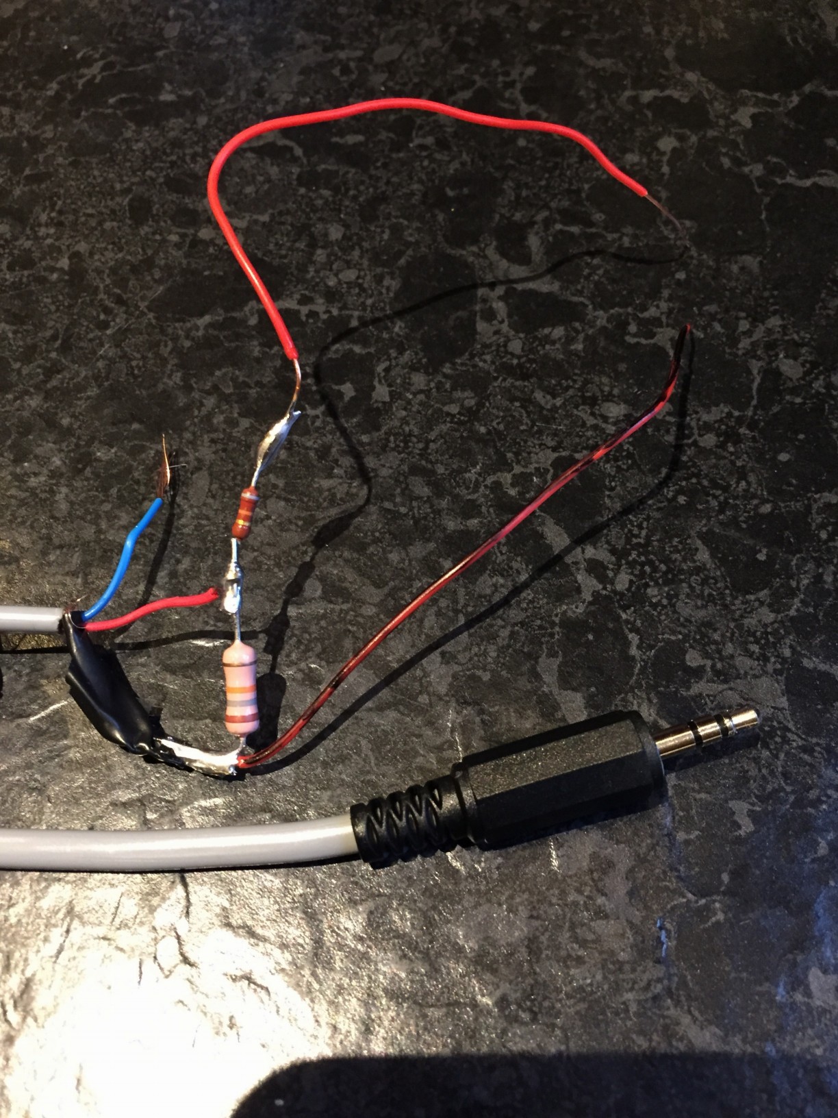
I didn’t go to the extent that Steven Hale did, I just wired up one channel, and didn’t bother with shrink wrap to make it look professional. This is probably a one-off tool for me.
Then:
- Arranged the receiver on the breadboard, powered by Raspberry Pi power via its header pins
- Connected the logic analyser probes to the GND and DATA pins of the receiver via the breadboard
- Plugged the stereo jack into my Mac’s line-in/mic port
- Fired up Audacity and hit record
- Operated the thermostat to cause it to send signals
Once I’d recorded some signals, I found them amongst the noise, and zoomed in to see them. But something was wrong…
This wasn’t the clear, decipherable, square-wave I was expecting.
When I looked at the levels, it was clear that I was only getting a very faint signal. I guessed it must be something to do with the line level on the Mac, and that the resistance of my analyser was pulling the signal too low. So I experimented…
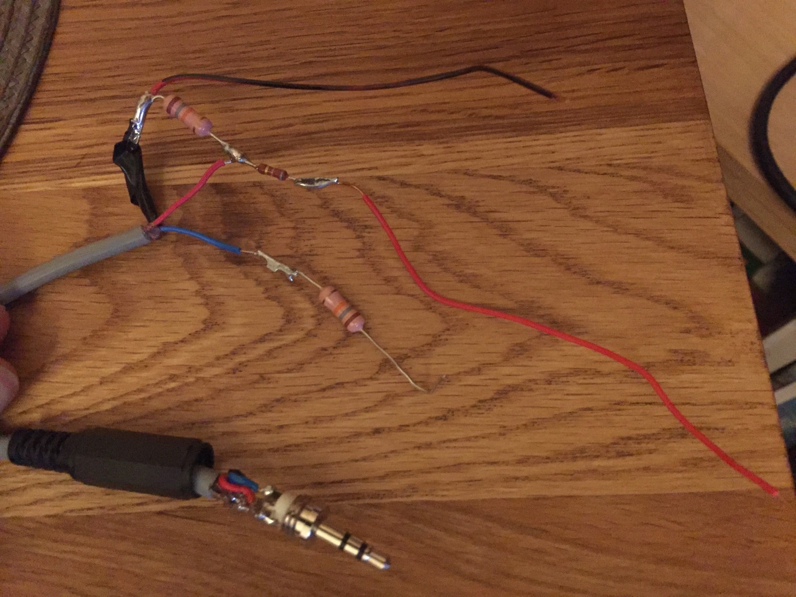
I modified the analyser to add a second 18k resistor on the unused lead. This time in series, rather than across the data and ground leads.
(NOTE: I was probably taking a bit of a risk here, that my soundcard might have been damaged by the higher voltages. But I figured “it’s 5V from a Raspberry Pi — what’s the worst that can happen?”. If you are following me, proceed with caution — I am no electronics engineer!)
Bingo. I had a signal. It appeared to be upside-down, so I flipped it in Audacity.
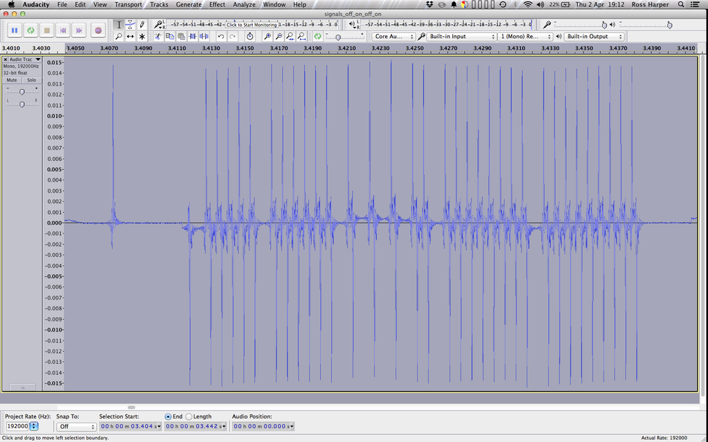
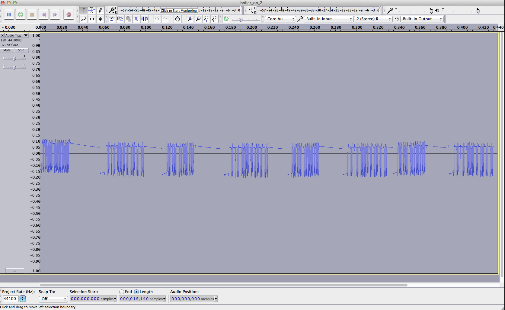
Here is the boiler ON signal when the noise either side is removed:
(I later flipped HIGH/LOW back in my program, I just found the signal easier to read this way round)
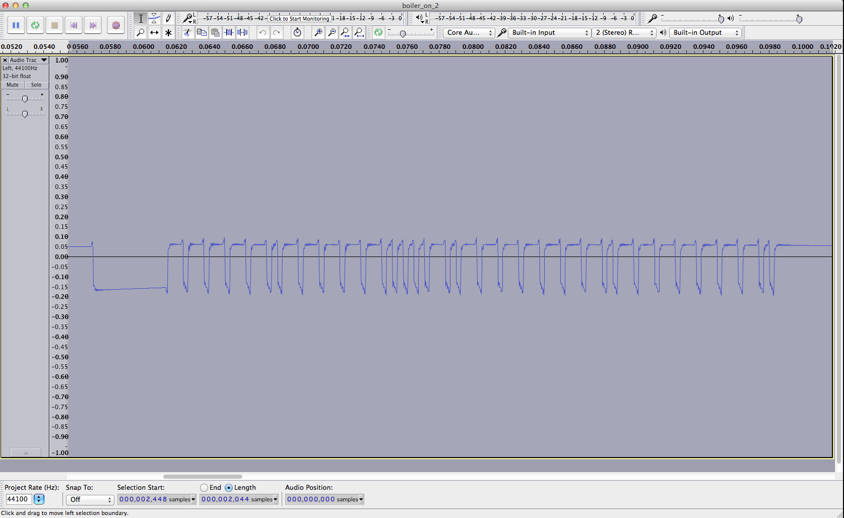
There appear to be a number of packets. Zooming in to an individual packet, we can see the individual HIGH/LOW signals.
The signal is pulled LOW for a period before the packet begins. There are also two different lengths of pulse: one must represent a binary ‘1’ and the other a ‘0’. I guessed that a long pulse would be a ‘1’ and the short pulse a ‘0’. Then I got to work reading all the individual 1s and 0s in the packets. I discovered that the packets were repeating and that for the ON signal there were just two packets:
    100001000101111010000000100000001
    111110111010000101111111011111110
It seems that:
- there are 33 bits per packet
- the first bit is always ‘1’, which must be a “start bit” that indicates the beginning of a packet
- the following 32 bits comprise the message
- the second packet is the opposite (bitwise NOT) of the first packet (excluding the start bit) I repeated the above for the OFF signal from the thermostat. These were the packets:
    100001000101111010000000100000000
    111110111010000101111111011111111
Now we can see that:
- the first 31 bits of the packet (excluding the start bit again) are the same in both the ON and OFF signals — this must be some sort of ID* — Update: it appears these aren’t always the same for all units – see below
- The final bit in the first packet indicates ON or OFF. 1 in the ON signal, 0 in the OFF signal
( * the ID is either hardcoded into the thermostat and learned by the receiver during pairing, or it is created and shared during pairing. I hope it is the former, as it would be a pain to have to keep sniffing a signal again if the receiver ever loses contact with the transmitter! I haven’t tested this yet.)
Now that I had the packet contents, there was one more thing left to determine: the timings of the pulses and the gaps between them. Using Audacity, I measured (in nanoseconds) the length of:
- the initial delay between the transmitter putting out a signal (HIGH), to beginning the first packet — this was measured from when the random noise stopped to when the signal was first pulled LOW
- the delay before the packet starts (from when it was pulled LOW to indicate a packet is coming, and when it goes HIGH for the first bit)
- a long pulse
- a short pulse
- the pause between pulses
- the delay between packets
Most of these are constant values, except the delay between packets which appears to be random. However, I just recorded each of these and will replay the same values each time in my boiler control program. If you are following this yourself in order to hack an RCR10, you probably don’t need to measure the lengths. You probably just need to decode the packets and plug the 1s and 0s into my boilercontrol program(see Update, below).
Replaying the Signals — Boiler Control Program
Now that I had sniffed the signals, it was time to see if I could replay them through my 433MHz transmitter, connected to my Raspberry Pi, to turn my boiler on and off. So, I created my “boilercontrol” program.
It’s written in C++, based on stuff I’d read on various blogs and websites that I don’t remember, and uses the WiringPi library to control the pins on the Raspberry Pi in order to send data to the transmitter. It’s written in C++ for two reasons:
- it compiles to native code that should mean it is more likely that the timings (that are measured in nanoseconds) will actually work
- it would be portable to an Arduino with only small changes — due to needing accuracy to tens of nanoseconds, I was concerned that the fact that the Raspberry Pi does not have a real-time operating system may throw the timings out too far or be unreliable. An RTOS would allow my code to run with deterministic timings. So if it didn’t work on the Pi, I could try on an Arduino.
The packet values and pauses are all hardcoded into the program currently. If I was doing my day job, and following proper software engineering practices, this would be configurable, and there would be unit tests… but this is a home project hack, so I won’t bother with that for now.
I tried this on the Pi… and it failed. No click from the boiler relay 🙁
To debug it, I set up my sniffer again. This time it would listen to the signals I was sending, rather than the original thermostat signals. Comparing my signals to the originals, I could see that they all seemed to be out a little: a little too long. Damned non real-time operating system! I can’t remember what the value was off the top of my head, but I recall it was in the region of 90ns. In true bodger style, I simply subtracted that from my values in the program and tried again.
Eureka! It worked! The boiler clicked on as I issued the command:
sudo ./callforheat 1
And off again with the command:
sudo ./callforheat 0
(the sudo was needed in order to access the pins via WiringPi — I believe this is no longer needed in the latest version of Raspbian at the time of writing)
Now I have a command that I can use, and write software around, to control my boiler. 🙂
Update — 30th March 2016
Github user PatchworkBoy found when he sniffed the code for his set that the on/off signals are not the same, exactly, like mine appeared to be. For his units, he found that the on/off codes were slightly different in in the middle too (at the 10th bit):
    ON packet pair
    1 0001 1000 0100 1000 0000 0001 0000 0001
    1 1110 0111 1011 0111 1111 1110 1111 1110

    OFF packet pair
    1 0001 1000 1100 1000 0000 0001 0000 0000
    1 1110 0111 0011 0111 1111 1110 1111 1111
Furthermore, he found that the timings (the gaps between packets and pulses etc) were also different. Therefore, if you are following this blog post and attempting to decipher the code for your own units, you’ll probably have to read both the on/off codes and measure them fully, as it appears you may not be able to assume that these details will be the same as they were for me.
